
Game Boy And Game Boy Color Eternal Life QSB Install
Required items for this install
An MBC3 Game Boy Game, check here to see if yours qualifies
Temperature Controlled Soldering Iron And Hot Air Gun (My iron and heat gun are set to 340°C or ~650°F)
Solder (I Use 60SN/40PB Solder by MG Chemicals, found Here)
Flux (I use a No clean flux paste syringe by MG Chemicals, Found here)
FM18W08 FRAM Chip Found at DIGI-KEY (FASTER SHIPPING) or ALI-Express (SLOWER SHIPPING)
Eternal Life QSB, BUY HERE
Wire (I use 28 AWG Stranded Silicone Wire, found HERE)
Kapton Tape, found HERE
STEP 1
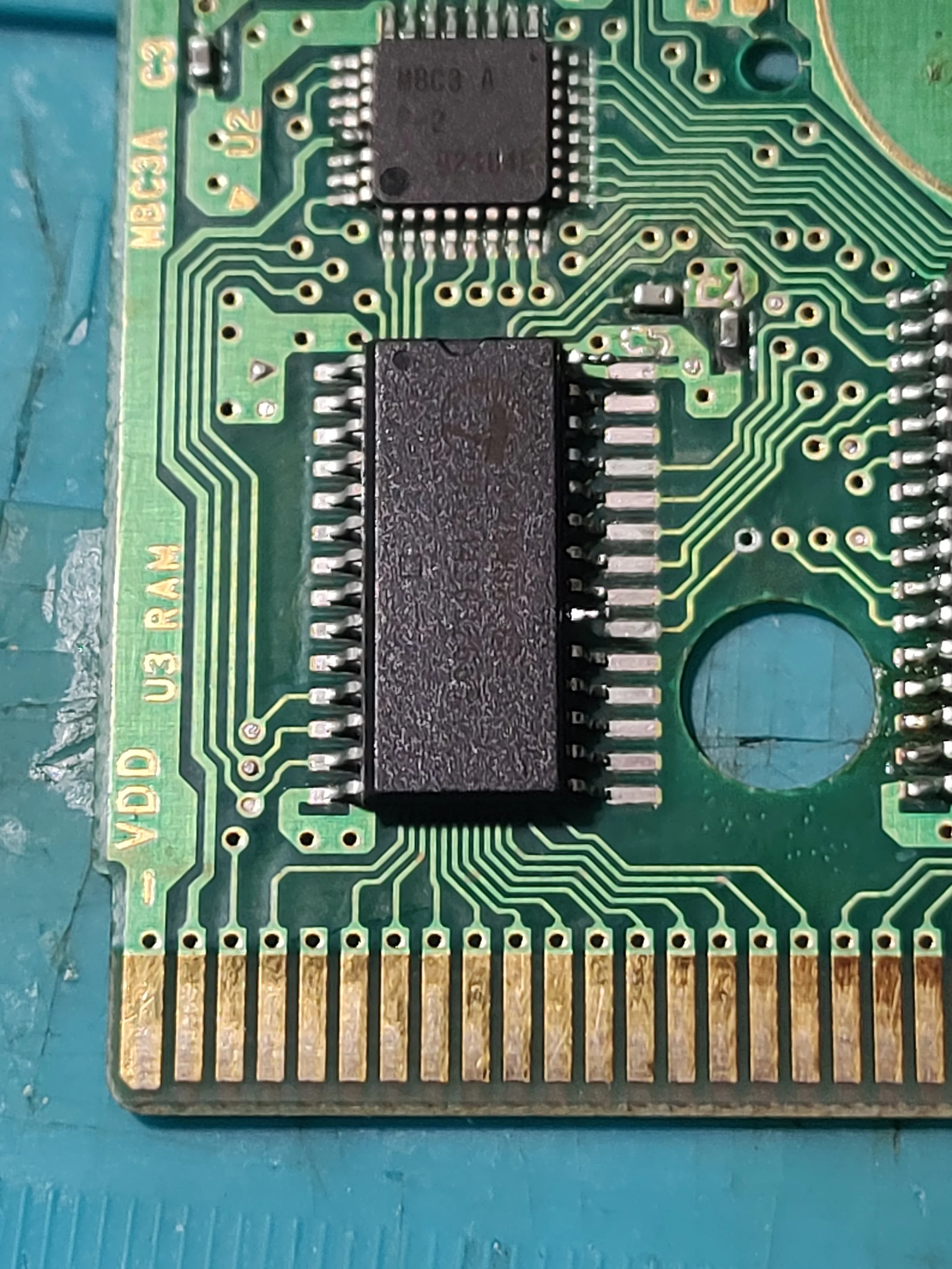
Preparing the cartridge


Remove the Save/Clock Battery


Using Hot Air, remove the SRAM chip (located on the left side of the board (I shoot at 340°C or ~650°F)
Using solder wick, wick off the left over solder from the pads where the sram was located

STEP 2
Preparing and installing the FM18W08

Lift pins 20 and 28 on the fm18w08 till roughly a 90° Angle


When Mounting the fm18w08, do your best get the legs on both sides close to where they need to be
once one side is perfectly aligned, tack one corner into place on the perfectly aligned side
once the other side is perfectly aligned, tack the opposite corner from the first tack
Apply flux on both sides of the chip
with solder on the tip of your iron, use a drag soldering technique to solder the rest of the legs to the board

STEP 3
Preparing and installing the Eternal Life QSB
With a cotton swab, clean the area we just worked on


place a square of kapton tape to the right of the fm18w08
Make sure to tin the pads on the bottom of the qsb prior to installation
place the qsb so both pegs align with pins 20 and 28 (the already lifted legs)
with hot air, aim towards pin 20 and 28 on the game pcb
Once the solder is molten, use a pair of tweezers to press down on the qsb (Be midful of the tiny smd components pont the qsb. you should see the solder on the pads of 20 and 28 react to you pressing down) then remove the heat while maintaining pressure on the qsb for 15 - 20 seconds
if installed properly, when lightly nudging the qsb, it should not move and the qsb should be flush with the game pcb


Solder pins 20 and 28 of the Fm18w08 to the respective pads on the qsb

STEP 4
Wiring CLK, GND, and 5V to the QSB


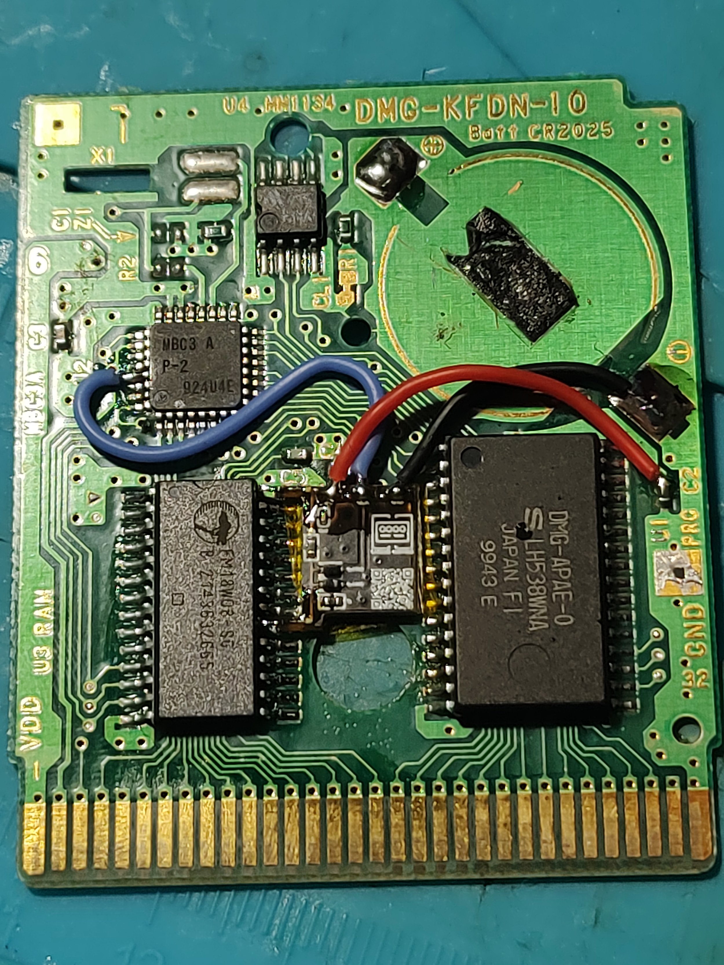

solder a wire (blue) onto pin 29 of U2 (5th pin on the left side, use of Flux is Recommended), this is clk
solder a wire (Black) to the negative (-) terminal where the battery used to be, this is gnd
solder a wire (Red) to the top of C2 (the point facing the negative (-) Battery terminal, use of flux is recommended), this is 5v
on the qsb, solder 5v to the left pad, clk to the middle pad, and gnd to the right pad
NOTE: if your game uses a real-time clock like pokemon gold, silver, and crystal, etc., you must reinstall the battery. The function of the battery is reduced to just keeping the time rather than keeping the time and keeping the save data alive.
once wired up, you’re finished soldering, if you used flux, clean that up using cotton swabs
OPTIONAL: You may put a dab of hot glue to the right side of the QSB to help tack it down a little better. i have strength tested these boards to see how well they stay on by throwing the game as hard as i can into a carpet numerous times, I was unable to make it break off. Hot glue would be more for peace of mind than anything and absolutely is not required for the install
STEP 5
Testing


if the, what would be, nintendo logo is a garbled mess, go back and check for shorts, any loose connections, or missing components on the qsb
If installed properly you should see an ungarbled nintendo logo when booting the game
play the game so you can make a save file, if it is still there after powering off the console, you have successfully performed the eternal life mod! Long live the saves!