
GameCube Controller Resources
Cable
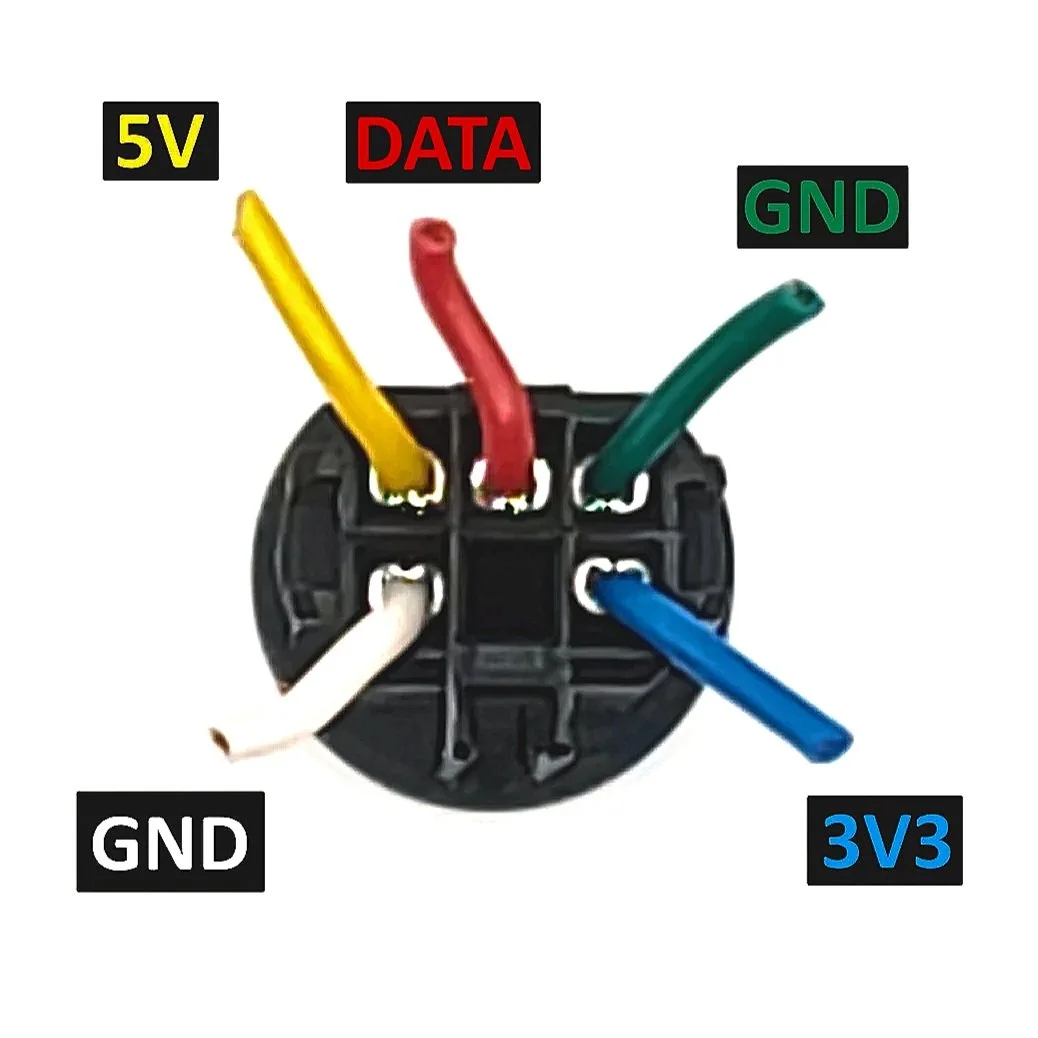
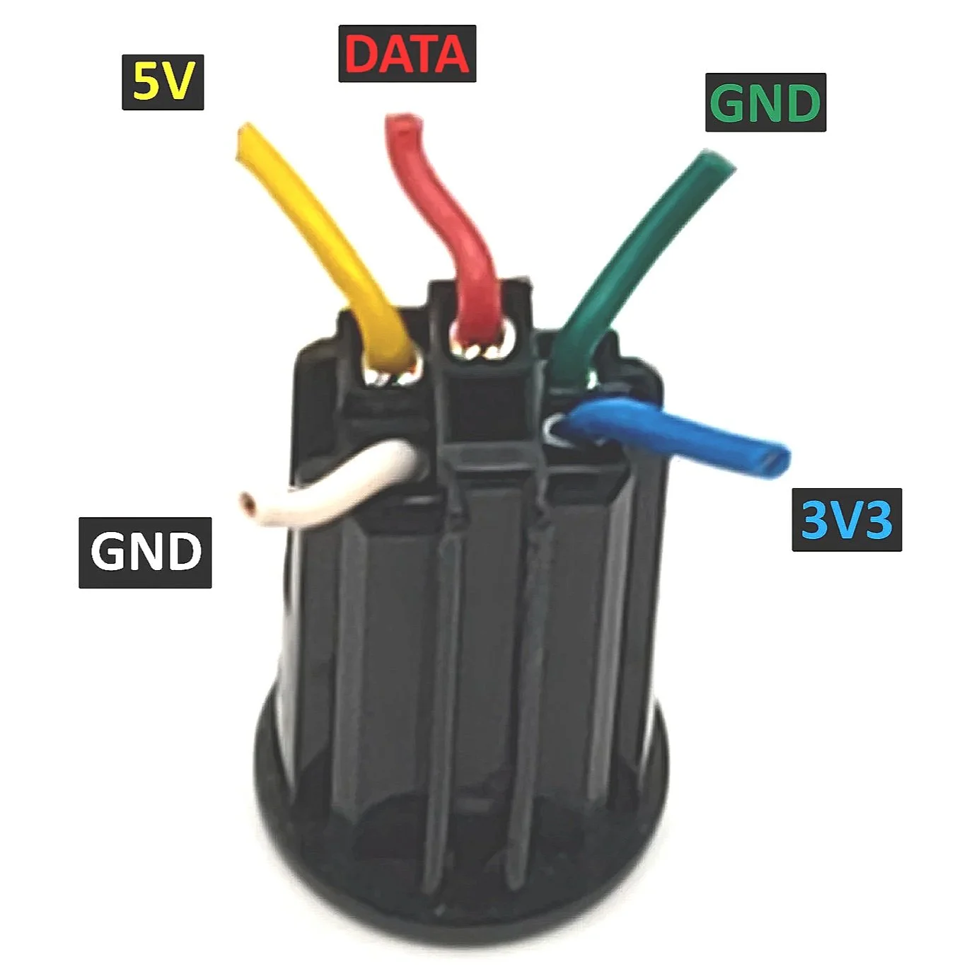
Plug End
Pin 1: 3.3 Volts
Pin 2: 5 Volts
Pin 3: BiDirectional Data Transfer
Pin 4: Ground
Pin 5: Ground (Rumble Ground)
Pin 6: Ground (Shield)
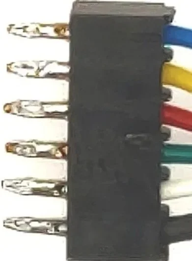
PCB End
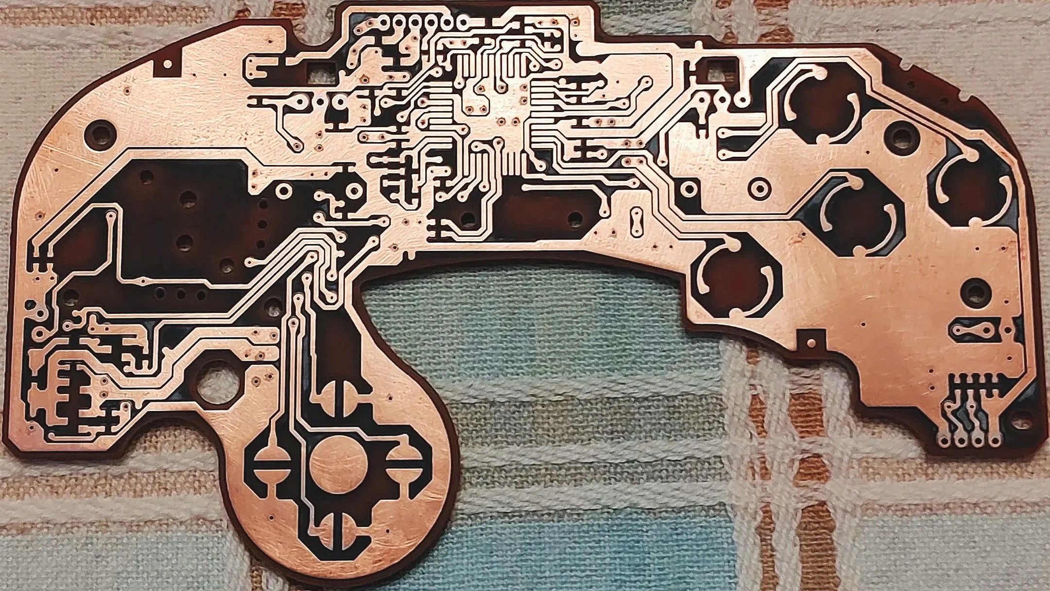
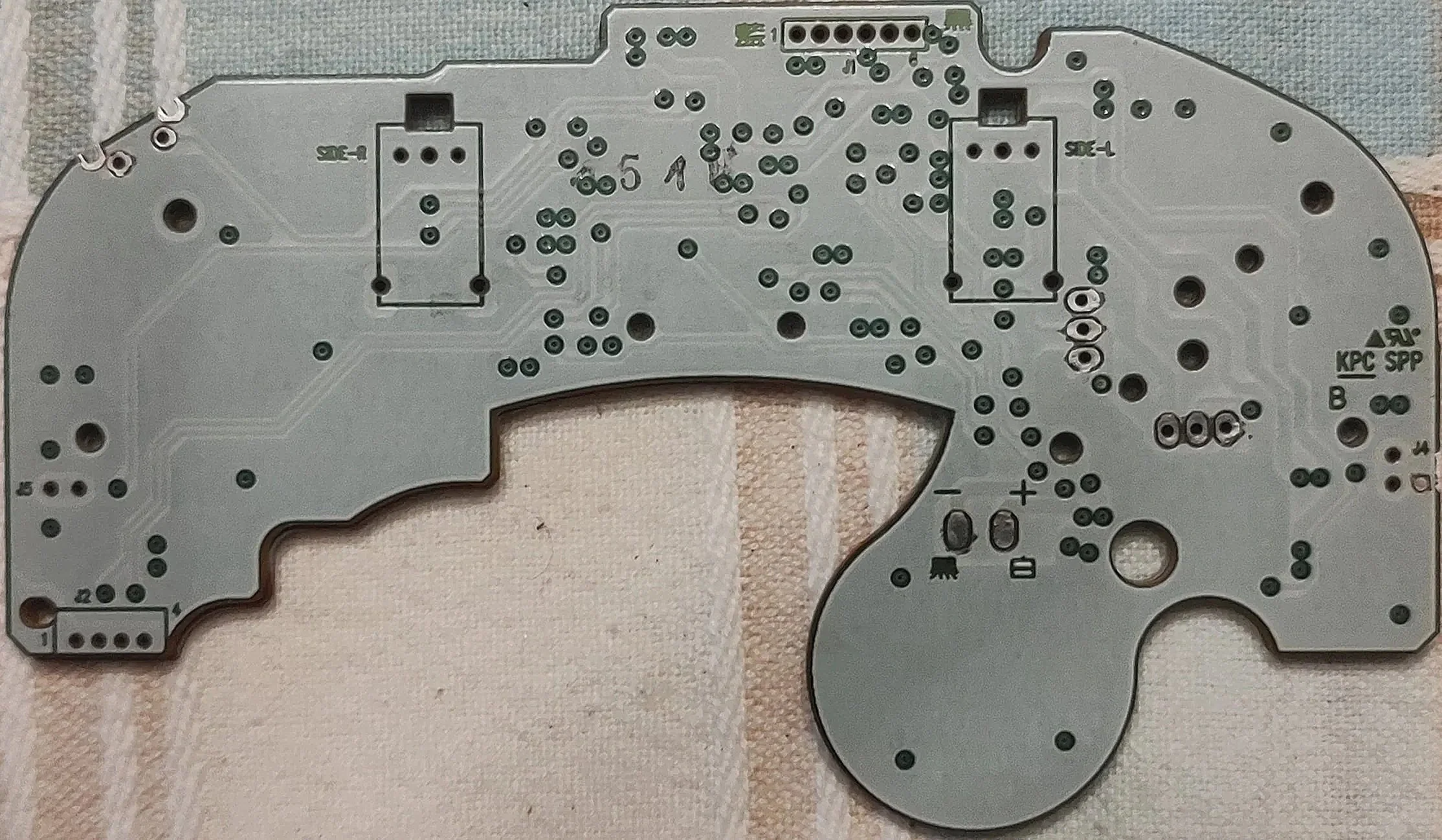
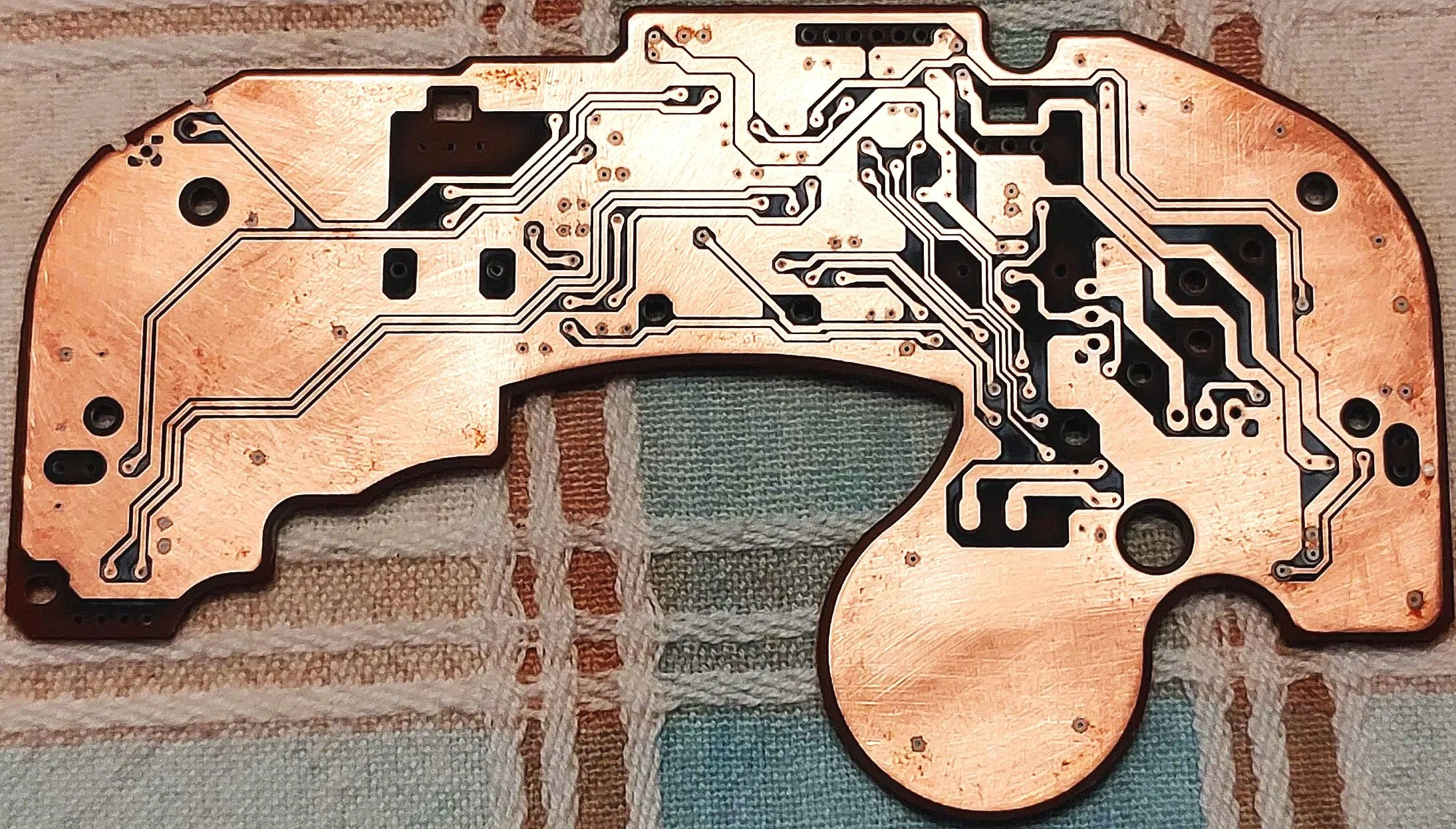
PCB
DIMENSIONS: 125.5mm wide, 73mm tall
FRONT SIDE (SIDE A)
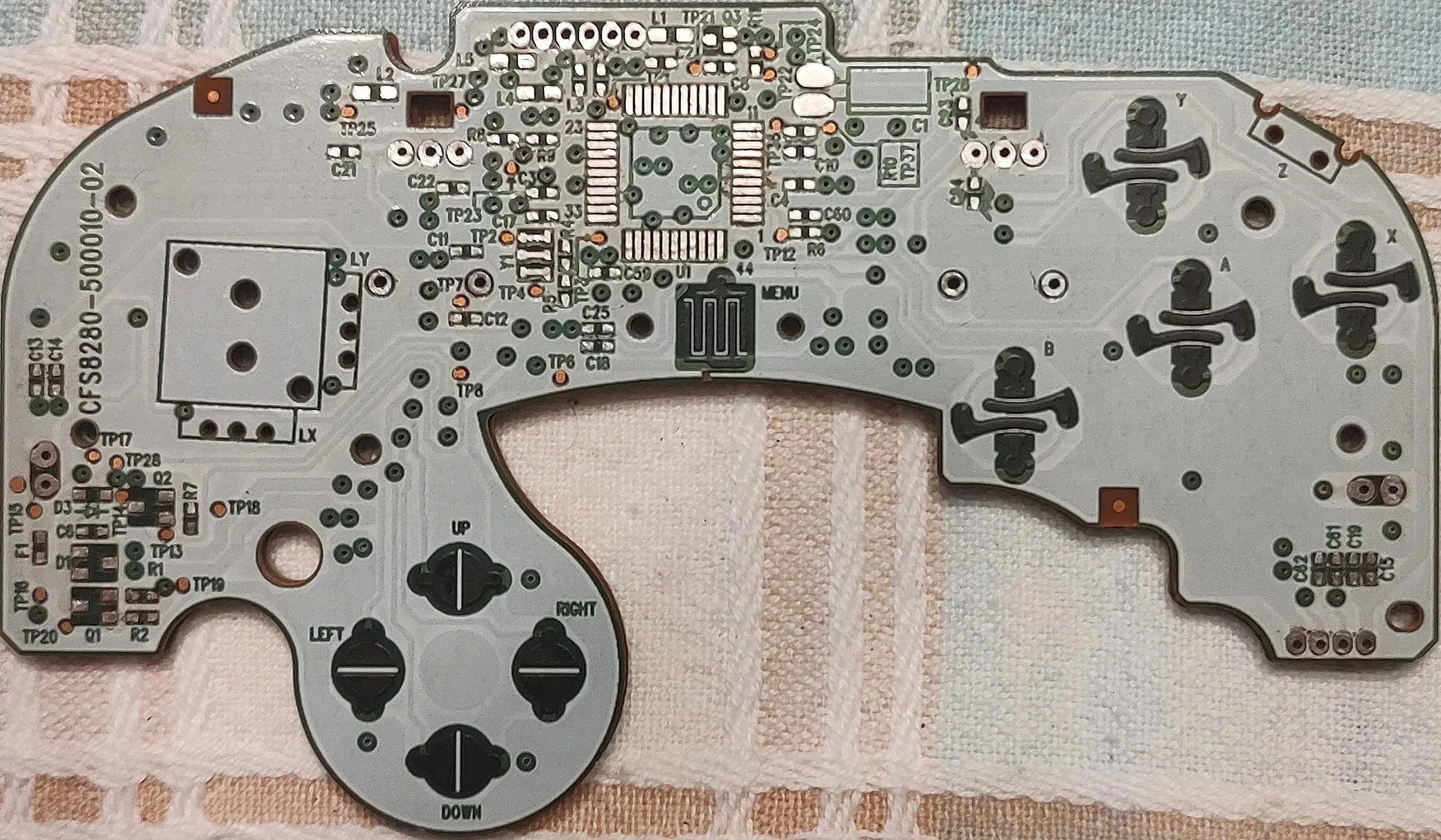
Back SIDE (SIDE B)
COMPONENTS
#0075FF = 3v3 (3.3 volts)
#FFEA00 = 5v (5 volts)
#FF0700 = Data Line
#15FF00 = Ground
#000000 = Ground (Rumble Ground)
#D600FF = Rumble Circuit
#959595 = Left Stick Components
#FED300 = C-Stick Components
#91FF88 = Analog Trigger Components
r1 - 10KΩ
r2 - 220Ω
r4 - 1MΩ
r5 - 680Ω
r6 - 220Ω
r7 - 220Ω
r8 - 750Ω
r9 - 100Ω
r10 - 390kΩ
r11 - 220Ω
L1 - 1.8uh
L2 - 1.8uh
L3 - 8.2uh
L4 - 1.8uh
L5 - 1.8uh
Q1 - SOT-23 PNP
Q2 - SOT-23 NPN
Q3 - NPN Epitaxial PlanAr Type
D1 - SOT-23 40V 500mA
D3 - SOD-323 50v 1A
Y1 - SMD4520-3p 4MHZ
F1 - 700 mA 50 V AC 50 V DC
J1 - 6 POS 2mm Pitch
J2 - 4 POS 2mm Pitch
J3 - 4 POS 2mm Pitch
J4 - 2 POS 2mm Pitch 26 AWG
J5 - 2 POS 2mm Pitch 26 AWG
Z - 4 POS 6.5 x 8.3 x 5 mm
SIDE-R - 30KΩ 15.8 x 9.0 x 7.8 mm
SIDE-L - 30KΩ 15.8 x 9.0 x 7.8 mm
LX - 30KΩ 10.1 x 10.7 x 4.3 mm
LY - 30KΩ 10.1 x 10.7 x 4.3 mm
RX - 30KΩ 10.1 x 10.7 x 4.3 mm
RY - 30KΩ 10.1 x 10.7 x 4.3 mm
C1 - 47uf 10v
c2 - 100nf
c3 - 100nf
c4 - 100nf
C6 - 100nf
c7 - 470nf
c8 - 22pf
c10 - 100nf
C11 - 100nf
C12 - 100nf
c13 - 100nf
c14 - 100nf
c15 - 100nf
C17 - 100nf
c18 - 47nf
C19 - 100nf
c21 - 100nf
c22 - 100NF
C23 - 100nf
c24 - 100nf
c25 - 47NF
c59 - 100nf
c60 - 330pf
c61 - 47nf
c62 - 47nf
CNT-DOL CHIP PINOUT
PACKAGE: QFN-44
Pins are read starting from the bottom-most pin on the right side and working their way counter-clockwise
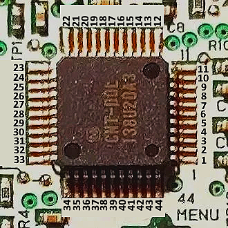
RIGHT SIDE
UP SIDE
12. Y
13. GND
14. X
15. GND
16. 3v3*
17. GND
18. TRANSMIT
19. 3v3
20. 3v3**
21. NC
22. Digital L
1. B
2. A
3. Rumble I/O
4. 3v3
5. Rumble Brake
6. Z
7. GND
8. Digital R
9. NC
10. UNKNOWN
11. UNKNOWN
LEFT SIDE
Down SIDE
34. 3v3
35. gnd
36. Analog L
37. LS X-Axis
38. LS Y-Axis
39. CS X-Axis
40. CS Y-AXis
41. GND
42. GND
43. GND
44. Analog R
23. D-Pad Left
24. D-Pad Up
25. GND
26. D-Pad Right
27. 3v3
28. D-Pad Down
29. NC
30. START
31. 3v3
32. CLK1
33. CLK2
*This line exclusively interacts with the data line and does not connect to the common 3.3 volt line
**This line does not connect to the common 3.3 volt line, it seems to control stick centering in some capacity
Shell
UNDER CONSTRUCTION
Mods
UNDER CONSTRUCTION